ElecAS
EleCAD: Single Line Diagram Software for Professional Electrical Engineers
EleCAD is browser-based single line diagram (SLD) software for professional electrical engineers, designers, electricians, contractors and project teams working to Australian and New Zealand standards. It is built to design a full distribution network, not to draw a picture of one: place the point of supply, main switchboard, distribution boards, busbar sections, submains, final subcircuits, protective devices, loads, PV and battery inverters, power factor correction banks and standby generators, and the whole network is solved as one electrical model. Draw and edit online with no install, no licence file and no plug-ins. What separates EleCAD from a drawing tool is that the diagram is a calculation model, not lines on a page: every cable carries conductor material, insulation, cores, installation method, length and derating; every switchboard tracks its busbar sections, incomer and outgoing ways; every protective device carries a real catalogue record with its trip curve, trip settings and breaking capacity; and every load contributes to the upstream maximum demand. From that model EleCAD runs a live design check on every circuit as you draw: AS/NZS 3008.1.1 current-carrying capacity after derating, per-segment and cumulative voltage drop against your limit with a reserve held back for final subcircuits, voltage rise from PV and battery inverters to AS/NZS 4777.1 with an optional site export limit, prospective short-circuit current (maximum and minimum) at every node, earth fault loop impedance built from the full R + jX loop including the earth conductor, the adiabatic I²t ≤ k²S² short-circuit withstand check on both the active and the earth conductor, device breaking capacity against the fault level where it is installed, discrimination between upstream and downstream devices, and maximum demand against the supply capacity. It also runs the studies that normally sit outside an SLD tool. Arc flash: IEEE 1584-2018 incident energy, arc flash boundary and PPE band at every three-phase board, with the clearing time read off the upstream device time-current curve at the arcing current rather than assumed, both the average and reduced arcing-current scenarios evaluated, and printable equipment labels. Standby supply: add a generator and a changeover (ATS or MTS) and the same installation is solved a second time running on the set, because an alternator fault level several times lower than the utility is the case that decides whether a breaker still clears an earth fault in time. Power factor correction: a capacitor bank on a board is sized from that board's own calculated demand and target power factor through the same engine as the standalone PFC calculator. Grid protection: once total inverter output passes 30 kW, the central CT, relay and per-inverter contactors the DNSP requires under AS/NZS 4777.2 are placed on the diagram, in the schedules and in the exports automatically. Cables can run as multiple parallel sets, with impedance, voltage drop and loop impedance divided across the runs, and earth conductors sized automatically or manually with their own parallel runs. Switchboards support multiple busbar sections with sub-bus groups, per-section protection, RCDs, incomers, contactors, shunt trips, metering outputs and spare poles, including dedicated essential-services sections. Every fault is listed with the fix that resolves it, and auto design sizes the cable and selects the protective device together until the two agree. An existing drawing does not have to be redrawn: upload a PDF or scanned single line diagram and the SLD reader extracts the boards, feeders, devices and loads, shows where each item came from on the sheet with a confidence score, lets you correct it, and lands it on the canvas as a live model. Export a branded PDF carrying the diagram, title block, legend, compliance summary and the cable, voltage drop, voltage rise, load, circuit breaker, switch, arc flash, grid protection, power factor correction and standby supply schedules, CSV schedules for cable, voltage drop, phase load and arc flash, or a DXF that opens in AutoCAD, Revit and BricsCAD as fully editable geometry. EleCAD pairs natively with the ElecAS calculator suite (cable size, voltage drop, maximum demand Tables C1/C2/C3, conduit sizing, arc flash, power factor correction, generator and UPS battery sizing), so the diagram and the calculations stay in lock-step. A practical alternative to AutoCAD Electrical, ETAP, EasyPower, PowerCAD and SmartDraw for Australian design, concept SLDs, tender drawings and project documentation.
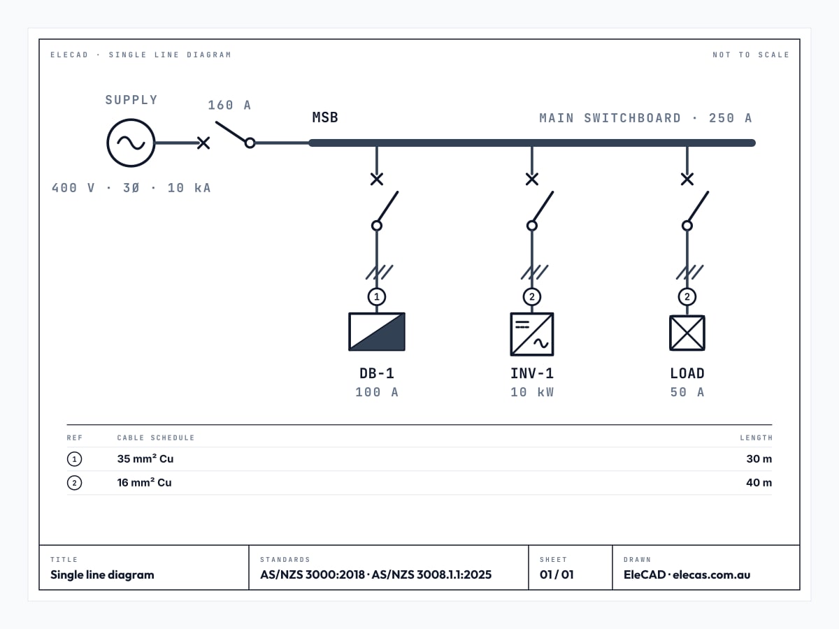
EleCAD: single line diagram software for professional engineers
EleCAD is single line diagram software for professional electrical engineers working to Australian and New Zealand standards. It is built to design a full distribution network rather than to draw a picture of one: the point of supply, the main switchboard and its busbar sections, every distribution board below it, the submains and final subcircuits between them, the protective devices with their real catalogue trip curves, the connected loads, embedded generation, power factor correction and standby supply are all one electrical model. Cable sizing to AS/NZS 3008.1.1, voltage drop, voltage rise, fault levels, earth fault loop impedance, discrimination, maximum demand and an IEEE 1584-2018 arc flash study run live on every circuit as you draw, and the whole network is solved a second time on the standby generator. It runs in the browser with no install and no licence file, and exports a branded PDF, CSV schedules and editable DXF.
EleCAD single line diagram software: key facts
- EleCAD is single line diagram software for professional engineers: it models and checks a full distribution network, not just the drawing of one.
- It is free and browser-based, with no install and no licence file.
- The diagram is a calculation model: EleCAD sizes every cable to AS/NZS 3008.1.1 using the same selection engine as the ElecAS Cable Size Calculator.
- A switchboard can carry its declared short-time withstand current Icw, and EleCAD judges it against the prospective fault at that board's bus with the AS/NZS 61439.1 Table 7 peak alongside; the board's diversity field also offers the AS/NZS 61439.2 Table 101 assumed loading factor for its number of outgoing ways.
- Nine compliance checks run live on every circuit as you draw: current-carrying capacity after derating, voltage drop, voltage rise to AS/NZS 4777.1, prospective fault current, earth fault loop impedance, adiabatic short-circuit withstand on the active and earth conductors, device breaking capacity, discrimination, and maximum demand against supply capacity.
- An IEEE 1584-2018 arc flash study runs on every three-phase board, reading the clearing time off the upstream device curve at the arcing current, and exports as a schedule and as printable equipment labels.
- Add a standby generator and a changeover (ATS or MTS) and the whole installation is solved a second time on the set, because the far lower alternator fault level is the case that governs disconnection times.
- Power factor correction banks are sized from the board demand, and central grid protection is placed automatically once site inverter output passes the 30 kW AS/NZS 4777.2 threshold.
- An existing PDF or scanned single line diagram can be imported: the reader extracts boards, feeders, devices and loads, shows its confidence and its sources, and lets you correct it before it lands as a live model.
- Circuits can run as multiple parallel cable sets, with impedance, voltage drop and earth loop impedance divided across the runs.
- Switchboards support multiple busbar sections with sub-bus groups, per-section protection and RCDs, and dedicated essential-services sections.
- Every fault is listed with the fix that resolves it, and auto design sizes the cable and picks the protective device together until the two agree.
- Diagrams export to a branded PDF with cable, voltage drop, voltage rise, load, circuit breaker, switch, arc flash, grid protection, power factor correction and standby supply schedules, to CSV, and to editable DXF for AutoCAD, Revit and BricsCAD.
- Drawing and editing needs no account; downloading the PDF or DXF requires a free ElecAS account and the download itself stays free.
- EleCAD is a desktop and laptop tool: the canvas needs a browser window at least 1024 pixels wide.
Who EleCAD single line diagram software is for
Professional electrical engineers, electrical designers, electricians, contractors, estimators, building services consultants and project managers in Australia and New Zealand designing, documenting or reviewing full distribution networks: single line diagrams, switchboard concepts, submain and final subcircuit design, protection and fault studies, arc flash assessments, standby supply arrangements and project documentation.
Standards EleCAD works to
- AS/NZS 3000:2018 (Wiring Rules)
- AS/NZS 3008.1.1:2025 (cable selection, derating and impedance data)
- AS/NZS 4777.1 (grid connection of inverters: voltage rise)
- AS/NZS 4777.2 (inverter requirements: central grid protection above the DNSP threshold)
- AS/NZS 3013 (essential services / fire-rated wiring systems)
- IEEE 1584-2018 (arc flash incident energy and arc flash boundary)
- Australian electrical drawing conventions
What EleCAD does: full network design, calculation and study features
- Built for professional engineers designing a full distribution network: point of supply, main switchboard, distribution boards, busbar sections, submains, final subcircuits, protection, loads and embedded generation solved as one electrical model rather than drawn as a picture.
- Free, online, browser-based: no install, no licence file, no plug-ins. Open any modern desktop browser and start drawing.
- Drag-and-drop palette for switchboards, busbars, loads, PV / battery inverters, standby generators, power factor correction banks, spare poles and a repeatable multi-unit bundle, plus inline isolators, circuit breakers, RCDs, fuses, contactors, transfer switches, MEN links, surge diverters and direct or CT metering.
- Cable sizing to AS/NZS 3008.1.1 on every run: copper, flexible copper or aluminium; V-75, X-90, R-90, X-110 and R-110 insulation; single or multi-core; full derating for ambient and soil temperature, soil thermal resistivity, depth of burial and grouping.
- Multiple cable sets: run any circuit as parallel cables, with impedance, voltage drop and earth loop impedance divided across the runs, and a separate parallel-run count for the earth conductor.
- Voltage drop checked per segment and cumulatively from the point of supply against your site limit, with a reserve held back for final subcircuits, and each board reporting the worst voltage drop anywhere downstream of it.
- Voltage rise to AS/NZS 4777.1: PV and battery inverters push current back up the mains, and the cumulative rise from the point of supply is checked against your limit, with an optional site export limit that caps it.
- Short circuit study: prospective three-phase fault current, maximum and minimum, computed at every node from the source impedance plus the accumulated cable impedance, with manual overrides for source Ze and Isc.
- Earth fault loop impedance from the full R + jX loop, including the earth conductor and its own parallel runs, checked against the trip current of the actual protective device fitted.
- Adiabatic I²t ≤ k²S² short-circuit withstand check on both the active and the earth conductor, plus a breaking-capacity check against the fault level where each device is installed.
- Multiple busbar sections per switchboard, with sub-bus groups for tied and jointed buses, per-section protection, RCDs, connectors, spare poles and dedicated essential-services sections that enforce 110°C insulation.
- Protection device library with real catalogue records (Schneider Electric or NHP): MCB curves B / C / D, MCCB, ACB, RCD, RCBO and HRC fuses, with editable trip settings and a discrimination check between upstream and downstream devices.
- Arc flash study to IEEE 1584-2018 on every three-phase board: incident energy, arc flash boundary and PPE band, with the clearing time read off the upstream device time-current curve at the arcing current rather than assumed, both the average and reduced arcing-current scenarios evaluated and the worse taken, and printable equipment labels.
- Standby supply as a second operating case: add a generator and an automatic (ATS) or manual (MTS) changeover, and the whole installation is solved again running on the set, so the far lower alternator fault level is checked against every disconnection time instead of the design passing on the mains figure alone.
- Generator sizing from the standby-backed board demand, using the same engine as the ElecAS Generator Sizing calculator, with the changeover, the standby lead and the backed sections drawn and scheduled.
- Power factor correction: a capacitor bank on a board is sized from that board's own calculated demand and your target power factor through the same engine as the ElecAS Power Factor Correction calculator, demand-neutral upstream, with its own feeder and protective device sized for the full capacitor design current.
- Central grid protection placed automatically once total inverter output passes 30 kW: the CT and relay on the main switchboard incoming chain and a contactor on every PV inverter feeder, as the DNSP requires under AS/NZS 4777.2, and removed again if the site drops back under the threshold.
- Import an existing drawing instead of redrawing it: upload a PDF or scanned single line diagram and the SLD reader extracts the boards, feeders, devices and loads, shows where each item came from on the sheet with a confidence score, lets you correct run lengths and load ratings, and lands the result on the canvas as a live model.
- Maximum demand aggregated up the tree to AS/NZS 3000, with per-board diversity and spare capacity, single-phase load allocation across L1 / L2 / L3, and a check of total demand against the substation or grid supply capacity.
- Live issue list: every fault is named with the circuit it belongs to and the fix that resolves it, and clicking it jumps straight to the setting to change.
- Auto design sizes the cable and selects the protective device together, iterating until the two agree, with a global cap on auto-selected cable size.
- Links directly into the ElecAS calculator suite: cable size, voltage drop, voltage rise, maximum demand (Tables C1, C2, C3), arc flash, power factor correction, generator sizing, UPS battery sizing.
- Export a branded PDF with the diagram, title block, legend, compliance summary and the cable, voltage drop, voltage rise, load, circuit breaker, switch, arc flash, grid protection, power factor correction and standby supply schedules.
- Export CSV schedules for the cable, voltage drop, phase load and arc flash tables, so a schedule drops straight into a spreadsheet or a switchboard build sheet.
- Export to DXF (AutoCAD, Revit, BricsCAD) as fully editable CAD vectors (layers, symbols, cables and labels), so your drafting team drops the SLD straight into their sheets.
- Upload your own SVG symbols, auto-layout the diagram, and undo or redo any edit one step at a time.
- Save the whole project to an .elecas file and reopen it later: a file written by an older version is laid out again on the way in, so it opens against the current geometry rules rather than the ones it was drawn to.
- Title block carries the project name, number, address, revision, company, designer, who it is prepared for and your own custom fields, and a drawing too large for one sheet is issued across A1 or A0 sheets with a sheet index and continuation titles.
- Tutorial mode walks first-time users through placing a source, switchboard, downstream loads, and exporting the diagram to PDF and DXF.
- A practical alternative to AutoCAD Electrical, ETAP, EasyPower, SmartDraw and Lucidchart for Australian electrical design.
How to draw a single line diagram in EleCAD
- Place the source and main switchboard: Open elecas.com.au/elecad, drag a supply source onto the canvas, then add the main switchboard. Tutorial mode walks first-time users through this exact flow. To start from a drawing you already have, upload a PDF or scanned single line diagram instead and review what the SLD reader extracts before it lands on the canvas.
- Add distribution boards and loads: Drag distribution boards, sub-boards, motors and loads onto the canvas and connect them. Each connection is a cable object carrying conductor, insulation and installation-method data.
- Set the protective devices: Assign MCBs (curve B, C or D), MCCBs, ACBs, RCDs, RCBOs or HRC fuses to each way from the Schneider Electric or NHP catalogue, and edit their ratings and trip settings in the switchboard editor. Add busbar sections where the board needs more than one bus.
- Enter cable and load data: Set conductor material (copper, flexible copper or aluminium), insulation (V-75, X-90, R-90, X-110 or R-110), phases, length, installation method, derating conditions and the number of parallel cable sets on each cable; set kW and power factor on each load. Demand, voltage drop, fault level and earth loop impedance update live.
- Add embedded generation, correction plant and standby supply: Drop PV or battery inverters, a power factor correction bank and a standby generator with its ATS or MTS changeover onto the network. Voltage rise is checked to AS/NZS 4777.1, the bank is sized from the board demand, central grid protection appears once site inverter output passes 30 kW, and the whole installation is solved again running on the generator.
- Clear the issue list and review the arc flash study: Work through the live issue list: each fault names the circuit it belongs to and the change that resolves it, and clicking it opens the setting to edit. Or leave cables and devices on Auto and let EleCAD size them together until every check passes. Then open the arc flash panel to see incident energy, boundary and PPE band at each board on the worse of the mains and standby supplies.
- Export the diagram: Export a branded PDF carrying the diagram, title block, legend, compliance summary and the cable, voltage drop, voltage rise, load, circuit breaker, switch, arc flash, grid protection, power factor correction and standby supply schedules, CSV schedules for a spreadsheet, printable arc flash equipment labels, or a DXF that opens as editable geometry in AutoCAD, Revit and BricsCAD. All are free with a free account.
EleCAD: designing full electrical networks on a single line diagram
Single line diagram software for professional engineers
EleCAD is a free, browser-based single line diagram (SLD) builder for Australian and New Zealand electrical design. You place sources, main switchboards, distribution boards, protective devices, cables and loads from a drag-and-drop palette, and the tool draws the diagram in Australian electrical drawing conventions. There is nothing to install and no licence to manage: the builder runs in any modern desktop browser.
Unlike a generic diagramming tool, every element is an electrical object. A cable is not just a line: it is a conductor with material, insulation, cores and an installation method. A distribution board tracks its incomer and outgoing ways; a protective device records its type, trip curve and breaking capacity; a load carries kW and power factor. That is what lets the diagram drive calculations instead of merely documenting them.
The unit of work is the whole network, not the single circuit. A calculator answers one question about one run; EleCAD holds the point of supply, every board below it, every submain and final subcircuit between them, the embedded generation, the correction plant and the standby supply as one connected system, and solves them together. Demand aggregates up the tree, fault level and loop impedance accumulate down it, and a change at one board reaches every circuit it affects. That is the difference between drawing a design and designing one, and it is why the output is suitable for issued documentation rather than only for concept work.
The diagram stays live as the design changes
Change a downstream load and the upstream maximum demand updates. Change a cable run and the voltage drop, fault level and earth loop impedance all follow. Because the model knows the electrical relationships between components, edits propagate the way they do in the real design, which keeps the SLD, the calculations and the documentation in step through design development.
Every board reports not just its own voltage drop but the worst voltage drop anywhere in the tree below it, so the circuit that will fail the check is visible from the switchboard rather than found by opening each final subcircuit in turn.
What EleCAD checks on every circuit as you draw
These are not checks you run at the end. Each one is recomputed on every edit, and any failure appears in the issue list against the circuit it belongs to, with the change that resolves it.
| Check | Basis | What EleCAD uses to run it |
|---|---|---|
| Current-carrying capacity | AS/NZS 3008.1.1 | Published capacity tables for the conductor, insulation, cores and installation method, derated for ambient or soil temperature, soil thermal resistivity, depth of burial and grouping. |
| Voltage drop | AS/NZS 3000 Clause 3.6 | Per-segment drop from cable impedance and undiversified current, summed from the point of supply, against your site limit less the allowance reserved for final subcircuits. |
| Voltage rise | AS/NZS 4777.1 | Cumulative rise from the point of supply to each PV or battery inverter from its rated output, capped by the site export limit where one is set. |
| Prospective fault current | AS/NZS 3000 | Source impedance plus the accumulated cable impedance at every node, reported as both a maximum and a minimum three-phase fault level. |
| Earth fault loop impedance | AS/NZS 3000 Appendix B | The full R + jX loop including the earth conductor and its own parallel runs, checked against the trip current of the device actually fitted. |
| Short-circuit withstand | AS/NZS 3008.1.1 Table 5.1 | The adiabatic I²t ≤ k²S² check, run separately on the active conductor and on the earth conductor. |
| Breaking capacity | Device catalogue rating | The rated breaking capacity of the selected device against the prospective fault current where it is installed. |
| Discrimination | AS/NZS 3000 | The rating of each feeder device against every downstream device on the same path. |
| Maximum demand | AS/NZS 3000 Appendix C | Connected load aggregated up the tree with per-board diversity and spare capacity, then checked against the substation or grid supply capacity. |
| Arc flash incident energy | IEEE 1584-2018 | The board's own bolted fault level and system voltage, with the clearing time read off the upstream device curve at the arcing current and an equipment preset for electrode configuration, gap, working distance and enclosure size. |
Parallel cable sets, earth conductors and multi-section switchboards
Real submains are often more than one cable. EleCAD runs any circuit as multiple parallel sets, and the parallel count is carried through the physics rather than bolted on for display: active impedance, voltage drop, voltage rise and the earth fault loop are each divided across the runs. The earth conductor carries its own parallel count when it is not integral to the cable set, and can be sized automatically or fixed manually with an upper bound.
Switchboards are modelled as more than a single bus. A board can carry several busbar sections, tied together into sub-bus groups where the design calls for it, each with its own rating, incoming protection, RCD arrangement, connector device and spare pole allowance. Sections flagged as essential services enforce 110°C elastomeric insulation on the cables feeding them, so a fire-rated requirement cannot be lost between the diagram and the cable schedule.
Protective devices from a real catalogue, not a symbol library
Each protective device on the diagram is backed by a catalogue record from Schneider Electric or NHP, selectable per project. That record carries the trip characteristic the checks depend on: MCB curve B, C or D, the thermal or electronic trip settings on an MCCB or ACB, and the rated breaking capacity. It is why the earth fault loop check can be run against the trip current of the device actually specified rather than a generic assumption, and why breaking capacity can be tested against the fault level at that point in the network.
Auto design closes the loop between the cable and the device. Sizing a cable changes the fault level and loop impedance, which changes which device is acceptable, which in turn changes the current the cable must carry: EleCAD iterates the two together until they agree, subject to a global cap on auto-selected cable size that you set on the source.
Arc flash: an IEEE 1584 study the diagram already has the inputs for
Every three-phase switchboard on the diagram carries an IEEE 1584-2018 incident energy study: bolted fault current, arcing current, clearing time, incident energy in cal/cm² at the working distance, the arc flash boundary and the PPE band that follows. Nothing extra has to be entered for it. The board already knows its own fault level from the network solve, the system voltage from the point of supply, and the upstream device from the incoming cable.
The clearing time is the reason this belongs on the diagram rather than in a standalone calculator. It is the input that makes an arc flash study slow: you find the arcing current, then read the upstream device curve at it by hand. EleCAD knows which device is fitted and what its trip settings are, so it reads the curve itself, at the arcing current rather than at the bolted fault current, and it evaluates both the average and the reduced arcing-current scenarios and takes the worse of the two, as IEEE 1584-2018 requires: a lower arcing current sits further left on the device curve and can clear far more slowly.
What the diagram genuinely cannot know is the physical equipment, so electrode configuration, conductor gap, working distance and enclosure size come from an IEEE 1584 equipment preset, defaulted by the board's role in the network and editable per board. Inputs that fall outside the model's validity range are flagged rather than quietly returned. The study exports as a schedule and as printable equipment labels, each carrying the worse of the mains and standby cases. It supports, and does not replace, a documented arc flash risk assessment and PPE program.
Standby supply: the same installation, solved again on the generator
A standby generator is not a symbol in EleCAD, it is a second operating case. Add a generator, choose an automatic transfer switch (ATS) or a manual changeover (MTS), and mark the busbar sections it backs, and the whole installation is solved a second time with the alternator as the point of supply, carrying its own short-circuit contribution and earth loop impedance.
This matters because a site fed from a 500 kVA transformer and the same site fed from a 125 kVA alternator have fault levels that differ by a factor of five, and the low one is the one that decides whether a breaker still clears an earth fault in time. Designing to the mains figure alone passes every check and leaves the installation unprotected for exactly the hours it is running on the set. The two results are held separately so the generator's far lower fault level can never be mistaken for the utility's, and the arc flash study ranks each board on the worse of the two supplies.
The set is sized from the demand of the sections it backs, through the same engine as the ElecAS Generator Sizing calculator, and the changeover, the standby lead and the backed sections are drawn, scheduled and exported with the rest of the network.
Power factor correction and grid protection
A power factor correction bank sits on a board's busbar as a shunt capacitor. It asks for a target power factor and nothing else: the load kW and the existing power factor are read off the board's own calculated demand, and the reactive-power maths runs through the same engine as the standalone ElecAS Power Factor Correction calculator, returning the required kVAr, the standard bank step, the resulting kVA and current reduction and the capacitance. The bank is demand-neutral upstream, because it supplies reactive power rather than drawing it, but its own feeder and protective device are still sized for the full capacitor design current.
Grid protection is placed for you. Once total PV and battery inverter output on the site passes 30 kW, a DNSP generally requires central grid protection instead of relying on each inverter's own AS/NZS 4777.2 protection: a relay sensing the mains through a CT and tripping a contactor in every inverter supply, so all generation disconnects on a grid fault. EleCAD lands the CT and relay on the main switchboard incoming chain and a contactor on each inverter feeder, carries them through the canvas, legend, schedules and both exports, and removes them again if the site drops back under the threshold. Confirm the required relay settings and any different threshold against your own DNSP connection requirements.
Importing an existing drawing instead of redrawing it
Much of the work on a real project starts from a drawing that already exists: an as-built, a tender sheet, a PDF from another consultant. EleCAD can read one. Upload a PDF or a scanned single line diagram and the SLD reader extracts the switchboards, feeders, protective devices and loads from the sheet.
Nothing reaches the canvas unreviewed, deliberately: a mis-assigned feeder produces a network that verifies cleanly and silently checks the wrong cable, which is worse than an import that fails outright. The review step shows what was read, where each item came from on the drawing, a confidence score against each, and every gap the drawing left behind. The two things a drawing can rarely tell you, run lengths and what a load actually draws, are editable there, and the import is built from your corrected version rather than from the raw reading.
Once it lands, it is an ordinary EleCAD model: cable sizing, voltage drop, fault levels, earth fault loop impedance, arc flash and maximum demand all run on it exactly as they do on a diagram drawn from scratch. That makes it a fast route into checking an existing installation, or into taking over a design someone else started.
Export: PDF for submissions, CSV for schedules, DXF for the drafting team
Diagrams export to a clean branded PDF for tender packages, design submissions and client review, carrying the diagram, title block, legend, compliance summary and the cable, voltage drop, voltage rise, load, circuit breaker, switch and isolator, arc flash, grid protection, power factor correction and standby supply schedules, plus printable arc flash equipment labels. The cable, voltage drop, phase load and arc flash schedules also export as CSV, so a schedule drops straight into a spreadsheet or a switchboard build sheet.
The DXF export carries fully editable CAD geometry with layers, symbols, cables and labels intact. It opens directly in AutoCAD, Revit and BricsCAD, so a drafting team can drop the SLD straight into their sheets without redrawing it. Both exports are free and require only a free account to download.
Single line diagram terms explained
Single line diagram (SLD)
- A simplified schematic of an electrical installation that represents each circuit with one line and a standard symbol rather than drawing every phase conductor separately. In Australian practice the SLD is the primary design document, showing the supply, switchboards, protective devices, cables and loads and how they connect.
One-line diagram
- The North American term for a single line diagram. The two names describe the same drawing; Australian and New Zealand documentation to AS/NZS 3000 conventions normally uses "single line diagram" or "SLD".
Main switchboard (MSB)
- The switchboard at the origin of the installation, fed from the consumer mains, that houses the main switch and the protective devices for the submains. On an SLD it is the first board downstream of the point of supply.
Distribution board (DB)
- A downstream switchboard fed by a submain that distributes final subcircuits to loads. In EleCAD a distribution board tracks its incomer, busbar sections and outgoing ways, so its total connected load aggregates upstream to the maximum demand.
Submain
- The cable between two switchboards: typically from the main switchboard to a distribution board. Submains carry the aggregated demand of everything downstream, which is why their size follows from the maximum demand calculation rather than from any single load.
Final subcircuit
- The cable from a switchboard to the point of connection of the equipment it supplies, protected by the outgoing device on that way. Final subcircuits are the last segment of the SLD and the one where AS/NZS 3008.1.1 current-carrying capacity and voltage drop are checked against the connected load.
Protective device
- The circuit breaker, RCD, RCBO or fuse protecting a cable against overload, short circuit and, where required, earth fault. In EleCAD each device records its type, rating and trip characteristic (MCB curve B, C or D), which is what allows the diagram to carry discrimination and disconnection-time context rather than just a symbol.
Maximum demand
- The highest current an installation or submain is expected to draw, assessed under AS/NZS 3000:2018 Appendix C using Table C1 (domestic), Table C2 (non-domestic) or Table C3 (the energy method). It sets the size of the consumer mains, submains and their protection.
Busbar section
- A separately identified length of busbar within one switchboard, with its own rating, incoming protection and outgoing ways: for example a general bus, an essential-services bus and a metered bus in the same board. In EleCAD sections can be joined into sub-bus groups where they are tied or jointed, and a section flagged as essential services enforces 110°C elastomeric insulation on the cables that feed it.
Parallel cable sets
- Two or more identical cables run in parallel to carry one circuit, used when a single conductor of the required capacity would be impractical to install or terminate. Running n sets divides the circuit impedance by n, which reduces both the voltage drop and the earth fault loop impedance; EleCAD carries the parallel count through all of those calculations rather than only showing it on the drawing, and the earth conductor keeps its own parallel count when it is not integral to the cable set.
Voltage drop
- The fall in voltage along a cable caused by its impedance and the current it carries. AS/NZS 3000 Clause 3.6 limits the total drop from the point of supply to any point of connection. EleCAD computes it per segment from the undiversified current, sums it along the path, and lets you reserve part of the site allowance for final subcircuits so submains are not sized to consume the whole budget.
Voltage rise
- The increase in voltage along a cable when embedded generation pushes current back toward the supply, which is the reverse of voltage drop and the limit that governs PV and battery inverter connections under AS/NZS 4777.1. EleCAD accumulates the rise from the point of supply to each inverter from its rated output, and an optional site export limit caps the current on the consumer mains and so reduces the rise.
Governing pair
- The pair in the path that gives up first: the one whose selectivity limit is the lowest, or that has no discriminating region at all. Fixing the path starts there.
Earth fault loop impedance (Zs)
- The total impedance of the path a fault current takes from the active conductor, through the fault, back along the earth conductor to the source: the source impedance Ze plus the active and earth impedance of every cable in the path. It must be low enough for the protective device to disconnect within the time AS/NZS 3000 requires. EleCAD builds the loop from the full R + jX of each segment, includes the earth conductor and its parallel runs, and tests it against the trip current of the device actually specified.
Adiabatic short-circuit withstand
- The check that a conductor will not exceed its permitted temperature during the time a fault takes to clear, expressed as I²t ≤ k²S² where k is the material and insulation constant from AS/NZS 3008.1.1 Table 5.1 and S is the conductor cross-sectional area. EleCAD runs it separately on the active conductor and on the earth conductor, because the earth is often the smaller of the two and is therefore the one that fails first.
Discrimination
- Also called selectivity: the arrangement of protective devices so that a fault is cleared by the device closest to it, leaving everything upstream energised. Losing discrimination means a single final subcircuit fault trips the main switch and blacks out the installation. EleCAD flags any feeder device rated at or below a device downstream of it on the same path.
Diversity
- The allowance made for the fact that not all connected load runs simultaneously, applied so that consumer mains and submains are sized for realistic maximum demand rather than the arithmetic sum of every load. In EleCAD diversity is set per board and applied to that board's children, with a separate spare-capacity allowance that can be diversified or not.
Derating
- The reduction applied to a cable's tabulated current-carrying capacity to account for the conditions it is actually installed in: ambient air or soil temperature, soil thermal resistivity, depth of burial, and grouping with other circuits. AS/NZS 3008.1.1 publishes a factor for each. EleCAD applies them per cable, so a run grouped in a hot ceiling space is sized differently from the same run in free air.
Arc flash incident energy
- The thermal energy a person at a given working distance would receive from an arcing fault, expressed in cal/cm² and calculated under IEEE 1584-2018 from the arcing current, the time the upstream device takes to clear it, and the physical geometry of the equipment. It sets the PPE category for work on that board. EleCAD computes it at every three-phase switchboard, reading the clearing time off the fitted device's own curve at the arcing current.
Arc flash boundary
- The distance from an arcing fault at which the incident energy falls to 1.2 cal/cm², the threshold for a second-degree burn to bare skin. Anyone inside it during energised work needs arc-rated protection. It is reported alongside incident energy for each board and printed on the equipment labels EleCAD exports.
Reduced arcing current
- A second IEEE 1584-2018 scenario run at a deliberately lowered arcing current, because a lower current sits further left on a protective device's time-current curve and can take far longer to clear, producing more incident energy than the higher current does. The standard requires both scenarios to be evaluated and the worse taken, which is what EleCAD does.
Transfer switch (ATS / MTS)
- The changeover device that connects a board to either its normal supply or its standby generator, never both. An automatic transfer switch (ATS) operates on loss of the normal supply; a manual transfer switch (MTS) is operated by hand. In EleCAD the changeover defines the second supply path, and the sections downstream of it are the ones the generator backs.
Standby operating case
- The condition in which the installation runs on its generator instead of the utility. It is a separate design case, not a variation on the normal one: an alternator's fault level is typically several times lower than the network's, so a protective device that clears an earth fault in time on the mains may not on the set. EleCAD solves the whole network twice and keeps the two results apart.
Power factor correction (PFC)
- Shunt capacitors installed at a board to supply reactive power locally, raising the power factor and reducing the current the upstream cable and transformer must carry. EleCAD sizes the bank from the board's own calculated demand and a target power factor, treats it as demand-neutral upstream, and still sizes its own feeder and protective device for the full capacitor design current.
Central grid protection
- A relay that senses the mains through a CT and trips contactors in the inverter supplies, disconnecting all embedded generation on a grid fault. Distributors generally require it in place of relying on each inverter's own AS/NZS 4777.2 protection once total inverter output passes a threshold, commonly 30 kW. EleCAD places the CT, relay and contactors automatically at that point and removes them if the site drops back below it.
DXF export
- Drawing Exchange Format: a vector CAD file format that AutoCAD, Revit, BricsCAD and other CAD packages open as fully editable geometry. Exporting an SLD to DXF preserves layers, symbols, cables and labels, so a drafting team can place the diagram directly onto a sheet without redrawing it.
Point of supply
- The point at which the electricity distributor's network ends and the consumer's installation begins, normally at the network meter or the origin of the consumer mains. On an SLD it is where the supply source is drawn and where earth fault loop impedance and voltage drop budgets start.
Single line diagram software: frequently asked questions
What is a single line diagram?
- A single line diagram (SLD), also called a one-line diagram, is a simplified schematic of an electrical power system that shows components (sources, switchboards, protective devices, cables and loads) using single lines and standard symbols instead of separate phase conductors. SLDs are the primary design and reference document for electrical installations in Australia, used for design submissions, tender drawings, switchboard schedules, commissioning and as-builts.
Is EleCAD free?
- Yes: EleCAD is free to use in your browser. Drawing and editing a single line diagram needs no account at all. Downloading the diagram as a PDF or DXF requires a free ElecAS account, and the download itself stays free with no watermark and no export cap. The paid Pro plan adds cloud save and sync across devices, project workspaces and folders, and your own logo and accent colour on exported PDFs.
Does EleCAD work in the browser without installing software?
- Yes. EleCAD runs entirely in the browser: Chrome, Edge, Safari and Firefox are all supported. There is nothing to download, no licence file to install, and no plug-in to enable. Diagrams are rendered locally so it works on any desktop or laptop, including locked-down corporate machines.
Does EleCAD work on a phone or tablet?
- No: EleCAD is a desktop and laptop tool. The canvas, palette and properties panel need a browser window at least 1024 pixels wide, so phones and smaller tablets are shown a prompt to reopen the page on a larger screen instead of a cramped canvas. The rest of the ElecAS calculator suite works on any screen size.
Can I export EleCAD single line diagrams to PDF or DXF?
- Yes. EleCAD exports your single line diagram to a clean, branded PDF suitable for design submissions, tender packages, client review and project files: the PDF carries the diagram, title block, legend, compliance summary and the cable, voltage drop, voltage rise, load, circuit breaker, switch and isolator, arc flash, grid protection, power factor correction and standby supply schedules, plus printable arc flash equipment labels. The cable, voltage drop, phase load and arc flash schedules also export as CSV for a spreadsheet or a switchboard build sheet. It also exports to DXF, which opens directly in AutoCAD, Revit, BricsCAD and other CAD packages as fully editable vector geometry (layers, symbols, cables and labels), so your drafting team can drop the SLD straight into their sheets.
EleCAD vs AutoCAD Electrical: what is the difference?
- AutoCAD Electrical is a heavyweight desktop CAD package licensed per seat: it is excellent for detailed schematics, panel layouts and large industrial projects but has a steep learning curve and high cost. EleCAD is a free, browser-based SLD builder focused on Australian single line diagrams and early-stage design: quick to learn, no install, and integrated with the ElecAS calculator suite. EleCAD is the right tool for concept SLDs, tender drawings, small-to-medium projects and any time AutoCAD would be overkill. The two also work together: EleCAD exports to DXF, so you can draft an SLD in the browser in minutes and open it in AutoCAD as fully editable geometry to finish it off.
EleCAD vs SmartDraw or Lucidchart for single line diagrams?
- SmartDraw and Lucidchart are general-purpose diagramming tools: they have electrical symbol libraries but no electrical engineering intelligence. EleCAD understands the actual electrical relationships: switchboards have busbars and incomers, cables have conductor material and installation method, loads contribute to maximum demand, protective devices have trip curves. That makes EleCAD substantially faster for real electrical design, with fewer mistakes carried into the calculations.
What symbols and components does EleCAD support?
- The palette places a supply source (utility connection or substation), switchboards, additional busbar sections, general loads, PV / battery inverters, standby generators, power factor correction banks, spare poles, and a bundle that drops a repeated set of unit supply circuits in one go. Devices are then placed inline on any busbar or cable: isolators and switches, circuit breakers (MCB curves B / C / D, MCCB, ACB), RCDs and RCBOs, HRC fuses, contactors, automatic and manual transfer switches, supply authority and multi-function meters in direct or CT connection, MEN links and surge diverters. Shunt trips and metering outputs are set on the devices that take them, and the grid protection CT, relay and inverter contactors appear on their own once the site passes the AS/NZS 4777.2 threshold. You can also upload your own SVG symbols to use as custom blocks. New symbols are added based on user requests via the Contact page.
Does EleCAD link to cable sizing and maximum demand calculations?
- It does more than link to them: it runs them. Every cable in EleCAD is sized by the same AS/NZS 3008.1.1 selection engine that powers the ElecAS Cable Size Calculator, reading the same published capacity, derating and impedance tables and the same circuit protection database, so a run sized on the diagram and the same run entered into the calculator return the same answer. Loads aggregate up the tree into the AS/NZS 3000 maximum demand at each board, and voltage drop, voltage rise, fault level and earth fault loop impedance are all computed on the diagram itself rather than being re-entered somewhere else.
Is EleCAD suitable for professional engineers designing a full network?
- That is what it is built for. EleCAD models the whole distribution network as one electrical system: the point of supply, the main switchboard and its busbar sections, every distribution board below it, the submains and final subcircuits between them, the protective devices with their real catalogue trip curves and breaking capacities, the connected loads, embedded generation and standby supply. Maximum demand aggregates up the tree, fault level and earth fault loop impedance accumulate down it, and every circuit is checked as you draw. Design decisions taken at one board propagate through the rest of the network the way they do on site, so it suits consulting engineers and designers producing issued documentation, not only concept sketches. The engineer remains the engineer of record: every output must be reviewed and signed off before issue.
Does EleCAD do arc flash calculations?
- Yes. EleCAD runs an IEEE 1584-2018 arc flash study on every three-phase switchboard on the diagram and reports the bolted fault current, arcing current, clearing time, incident energy in cal/cm², arc flash boundary and the PPE band that implies. The part that normally makes an arc flash study slow is the clearing time: you have to find the arcing current, then read the upstream device curve at it by hand. EleCAD already knows the device, so it reads the curve itself, and it evaluates both the average and the reduced arcing-current scenarios and takes the worse, as IEEE 1584-2018 requires. Equipment geometry (electrode configuration, gap, working distance, enclosure size) comes from an IEEE 1584 preset defaulted by the board's role in the network and editable per board. The study exports as a schedule and as printable equipment labels. It supports, and does not replace, a documented arc flash risk assessment and PPE program.
Can EleCAD model a standby generator and a changeover?
- Yes, and it treats the generator as a second operating case rather than a symbol. Add a generator, choose an automatic (ATS) or manual (MTS) changeover and mark the sections it backs, and EleCAD solves the whole installation a second time running on the set. This matters because an alternator fault level is often several times lower than the utility's, and the low figure is the one that decides whether a breaker still clears an earth fault in time: a design checked only against the mains can pass every check and leave the installation unprotected for the hours it is actually on the generator. The set is sized from the backed board demand using the same engine as the ElecAS Generator Sizing calculator, and the arc flash study reports both the mains and generator cases and ranks each board on the worse of the two.
Does EleCAD handle power factor correction and grid protection?
- Both. A power factor correction bank placed on a board is sized from that board's own calculated demand and your target power factor through the same engine as the ElecAS Power Factor Correction calculator: it returns the required kVAr, the standard bank step, the resulting current reduction, and the design current its own feeder and protective device must carry. The bank is demand-neutral upstream, so it does not inflate the mains. Grid protection is automatic: once total PV and battery inverter output on the site passes 30 kW, the central CT and relay land on the main switchboard incoming chain and a contactor lands on every inverter feeder, which is the arrangement a DNSP requires in place of relying on each inverter's own AS/NZS 4777.2 protection. Both appear on the canvas, in the legend, in the schedules and in the PDF and DXF exports, and are removed again if the site drops back under the threshold.
Can I import an existing single line diagram instead of redrawing it?
- Yes. Upload a PDF or a scanned single line diagram and the EleCAD SLD reader extracts the switchboards, feeders, protective devices and loads from the sheet. Nothing lands on the canvas unreviewed: you are shown what was read, where each item came from on the drawing and a confidence score for it, along with every gap the drawing left behind. The two things a drawing usually cannot tell you, run lengths and what a load actually draws, are editable in the review step, and the import is built from your corrected version. Once imported, the drawing is a live model: cable sizing, voltage drop, fault levels, earth fault loop impedance, arc flash and maximum demand all run on it like any diagram drawn from scratch, which makes it a practical way to bring an as-built or a tender drawing into a check.
Can I share or collaborate on diagrams?
- Diagrams are shared today by export: a branded PDF for review and submission, or a DXF your drafting team can open in AutoCAD, Revit or BricsCAD and edit directly. Real-time multi-user collaboration is on the roadmap: sign in to your ElecAS account to be notified when it ships.
Is EleCAD suitable for AS/NZS 3000 design submissions?
- EleCAD is suitable for the single line diagram component of an AS/NZS 3000 design submission, tender package or as-built drawing set. As with any electrical design tool, the user remains the engineer of record: every diagram, calculation and design decision must be reviewed and signed off by a qualified electrical professional before issue, construction or energisation. See the Verification page for the engineering review process behind ElecAS.